Hello,
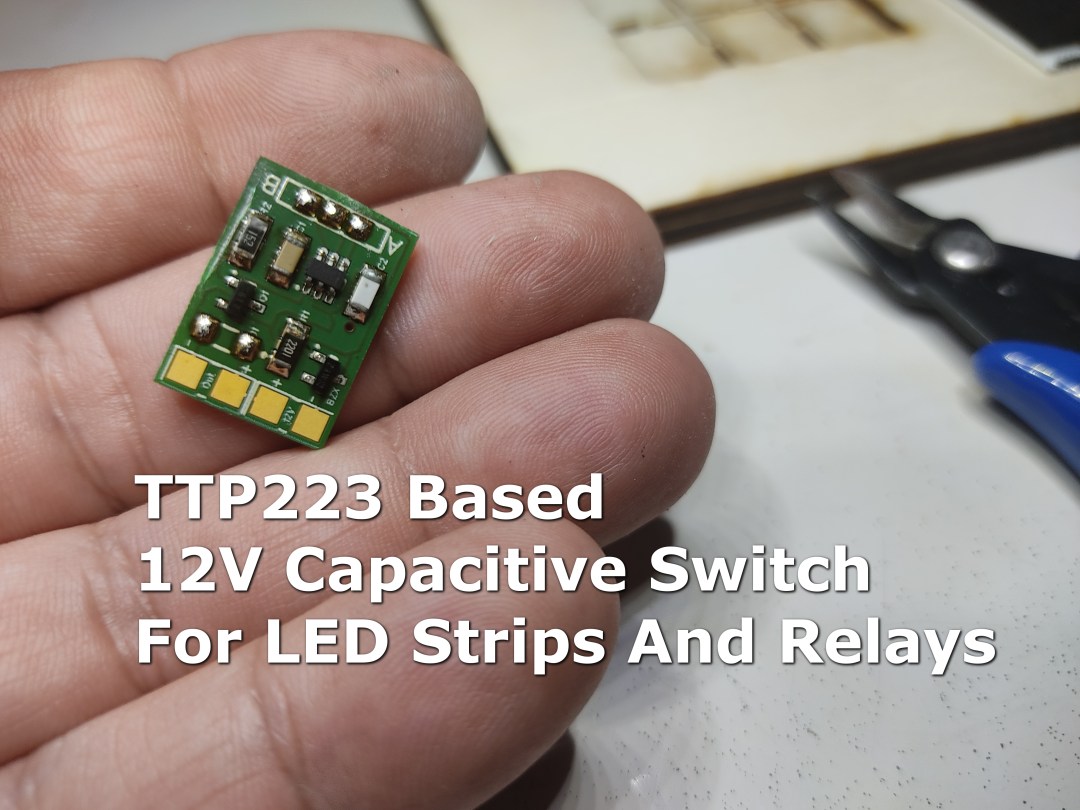
I built another LED lamp and wanted to use a TTP223 capacitive switch as usual. But Led Stripes have 12V and there was my problem again, the available TTP223 boards are 3-5V and have only a small switching current. Besides, I don’t need the LED on the board.
So I built a prototype with what I had lying around.
- 1 TTP223
- 1 Zener Dioder 5.1V
- 1 2k2 Resistor
- 1 1k5 Resistor
- 1 BD137 Transistor
All files can be found here: https://github.com/awall9999/Capacitive-Touch-Switch-12V
Here the first Schematic and Prototype:
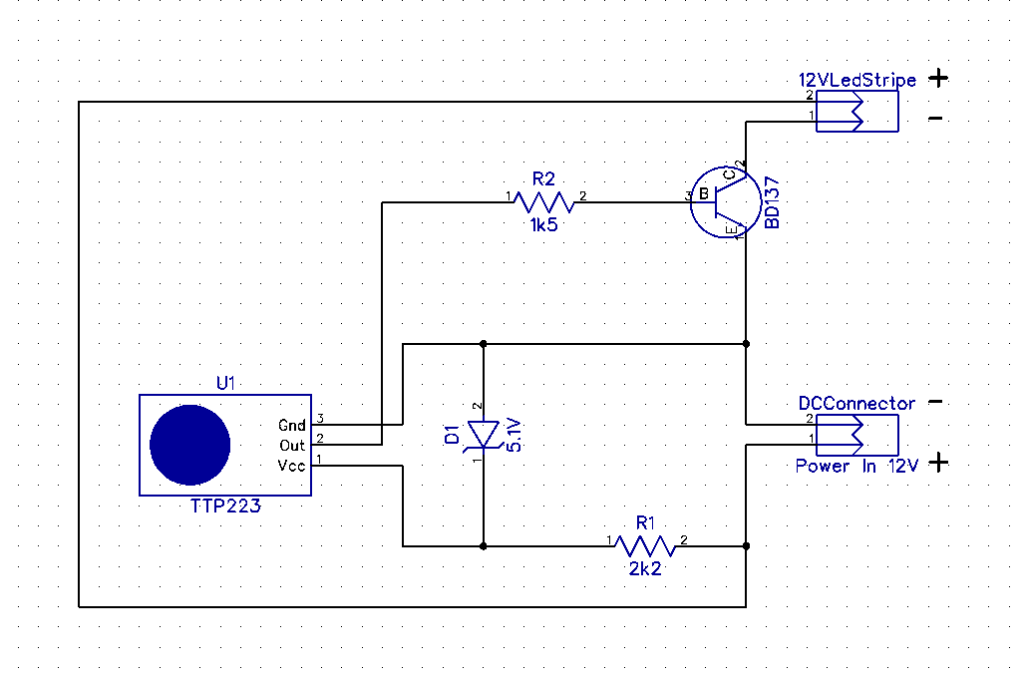
As you can see, this works very well.
PCB Design
First the schematic. I also included a flyback diode in the design, so you can also directly control a relay. The TTP223 chip has the same components as on the small original board. As on that, the 22pf capacitor is optional and is used to control the sensitivity of the touch controller. An FMMT617-625 comes into play as the transitor. You can also use another one. However, according to the data sheet, this one delivers 18V 3A. But I won’t go over 2.5A, just to be on the safe side 🙂
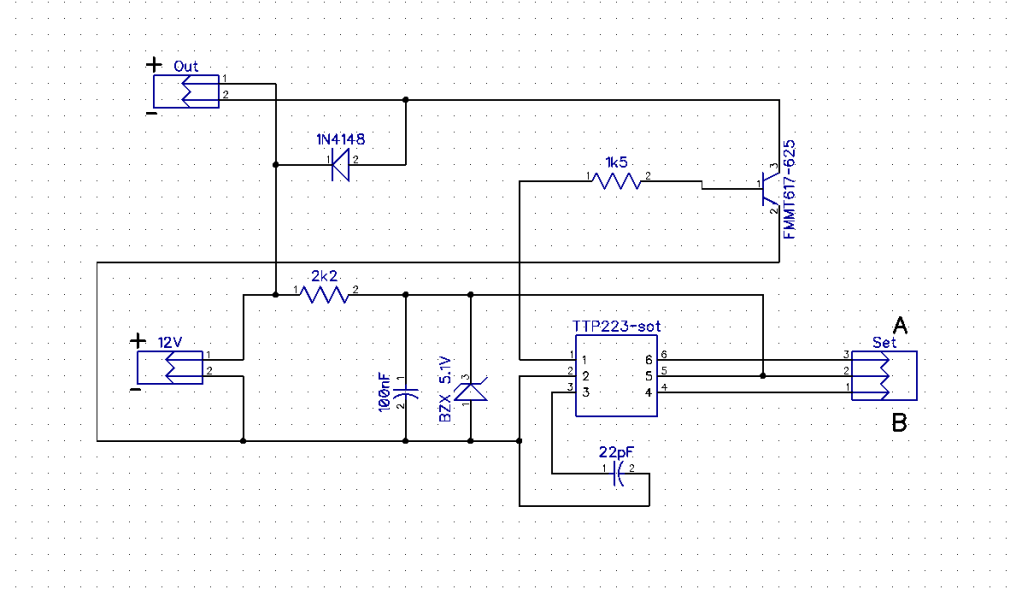
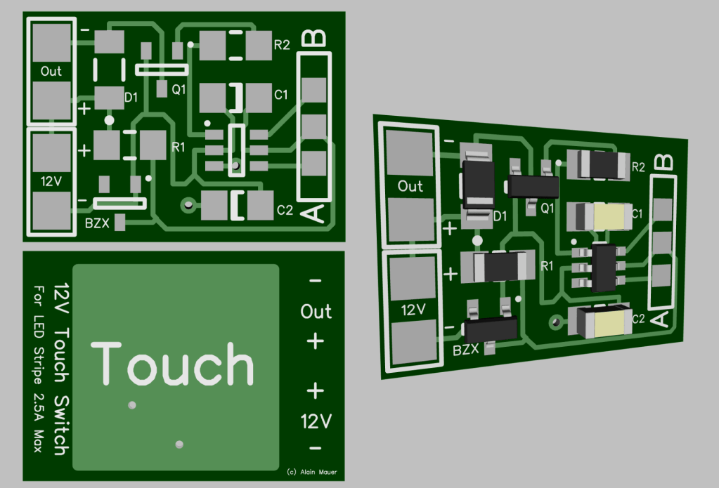
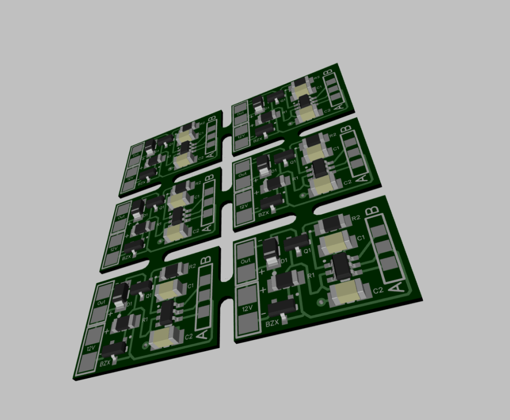
This is the design I sent to https://aisler.net/ who make the PCB’s for me.
Aisler is in Germany and definitely a competitor to China for prorotyping.
All files can be found here: https://github.com/awall9999/Capacitive-Touch-Switch-12V
Part List
- 1 TTP223 SOT23-6 Chip
- 1 Q1 FMMT617-625 SOT23 Transistor or equivalent
- 1 D1 1N4148W SOT123 (optional)
- 1 BZX BZX84 4.7V or 5.1V SOT23
- 1 R1 Resistor 2k2 1206
- 1 R2 Resistor 1k5 1206
- 1 C1 Capacitor 100nF 1206
- 1 C2 Capacitor 22pF 1206 (optional)
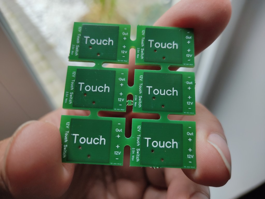
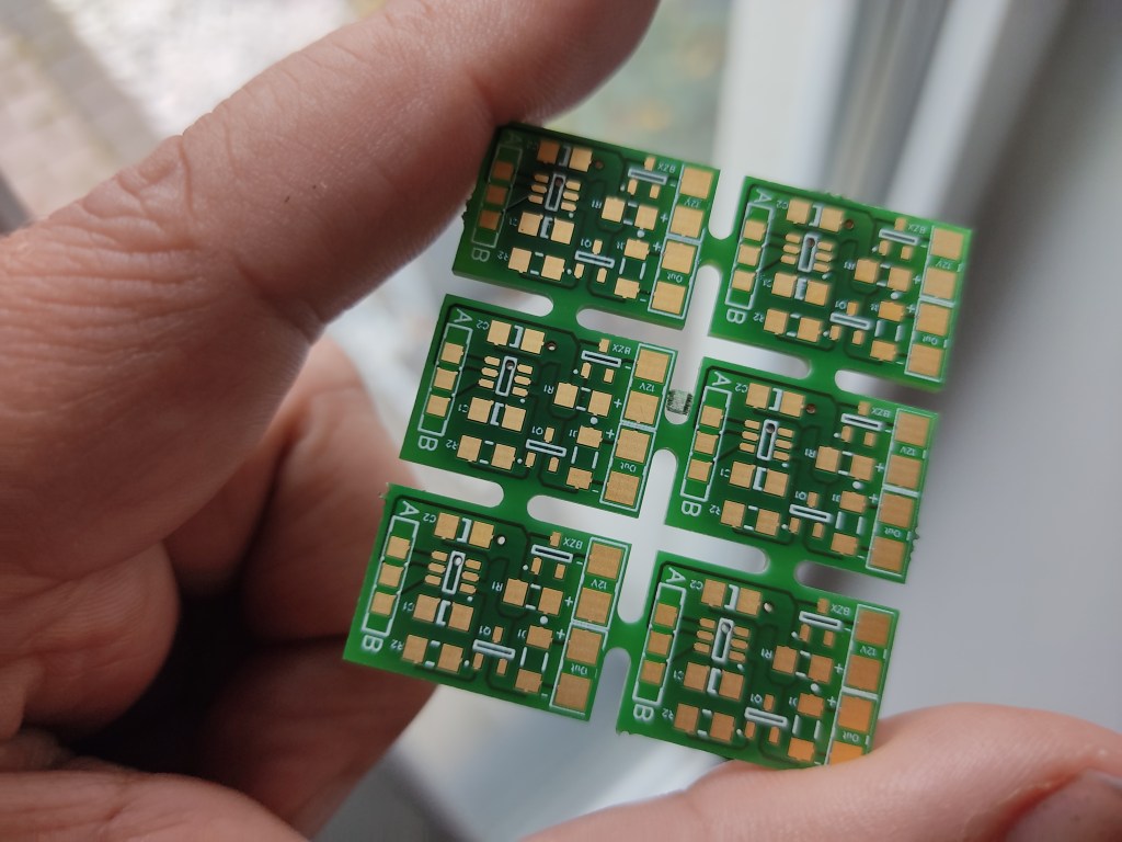
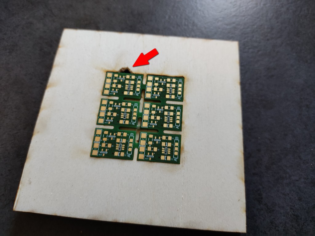
The PCB´s Are Here
8 days after ordering, the prototype PCBs finally arrived. They look simply great.
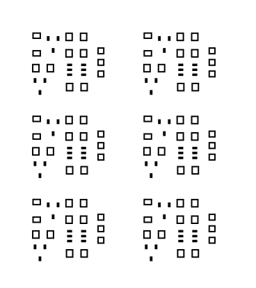
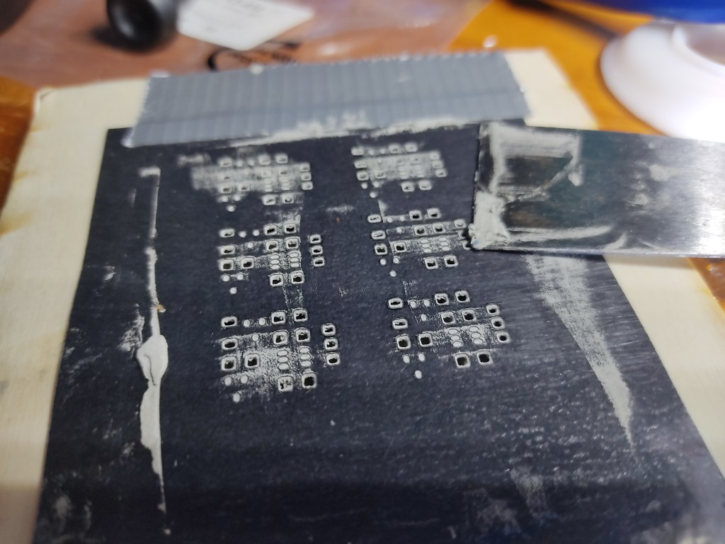
Stencil
How do I make my stencil?
First I laminate a white or black sheet of paper or thin cardboard into the foil. The paper is for visibility afterwards, so that you can position the holes better.
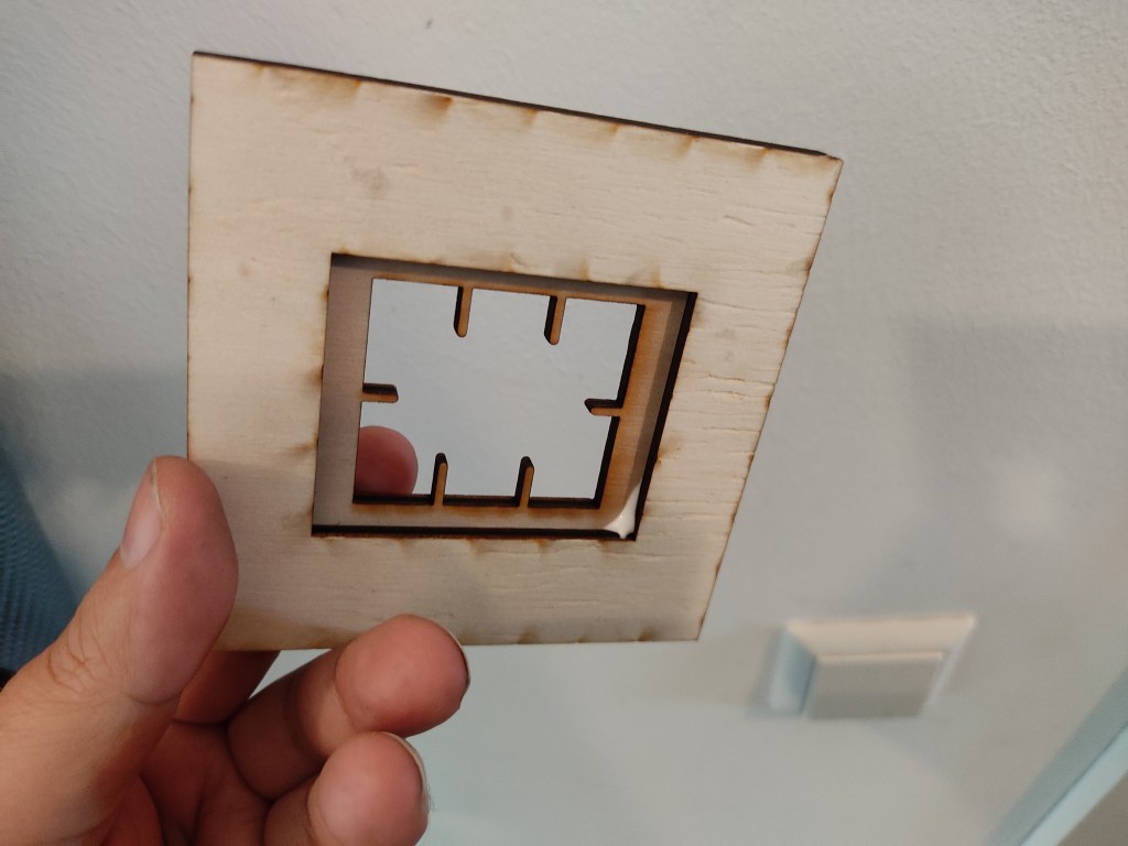
Then I put the whole thing through the laser cutter and it’s done.
Most of the time, this works quite well.
Applying The Solder Paste
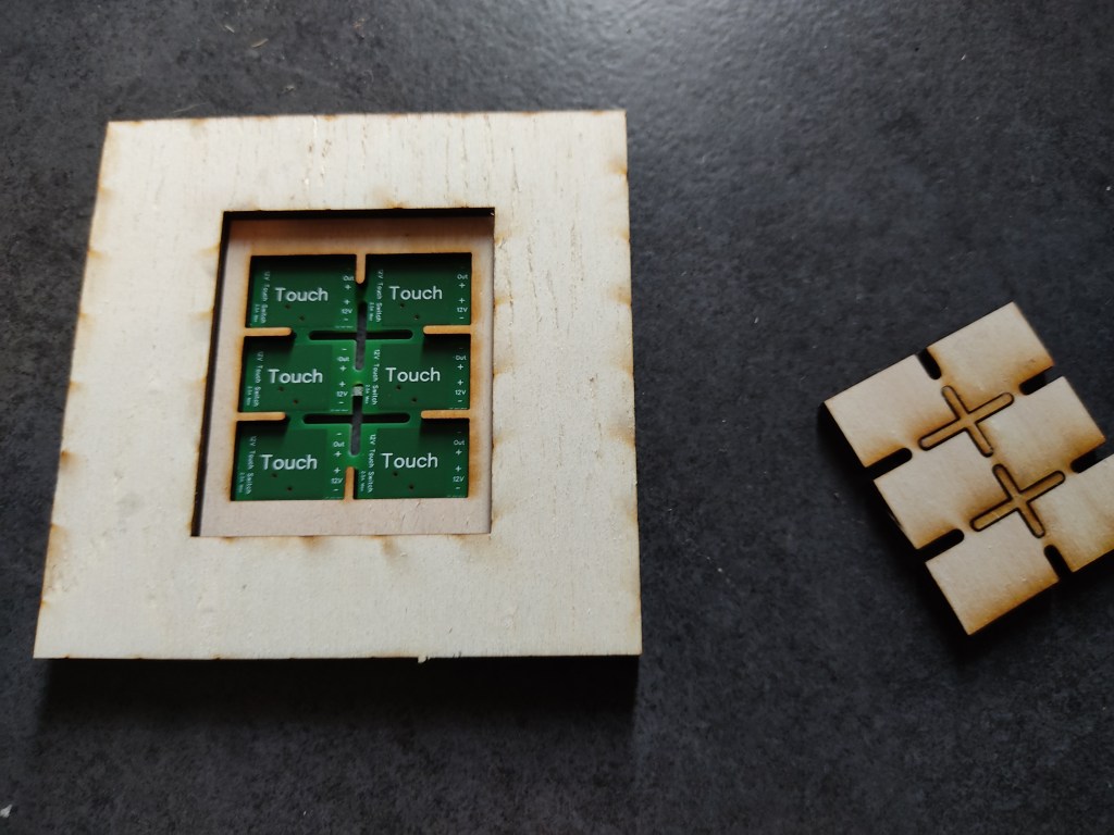
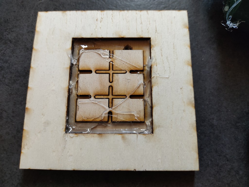
First I built a PCB holder.
The PCB can be flush with the surface. This simplifies the application of the soldering paste. I have added a small notch to make it easier to remove the pcb. (red arrow)
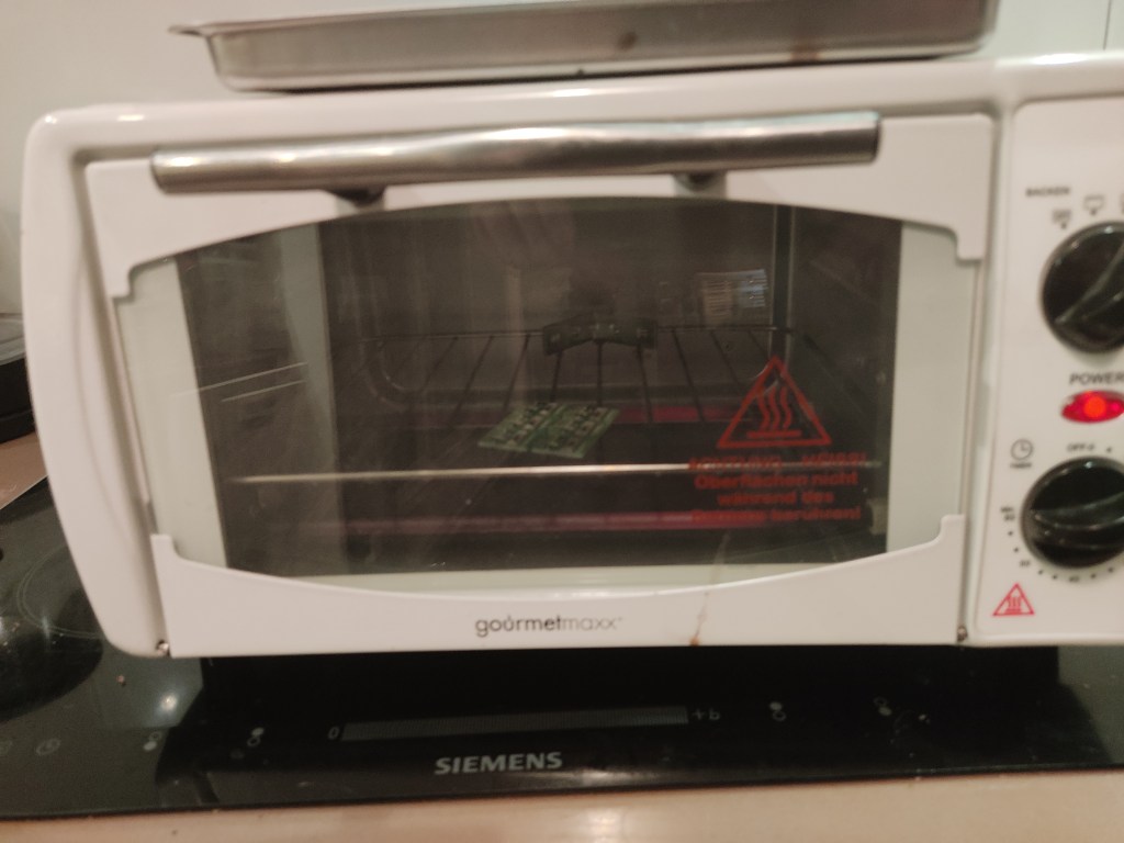
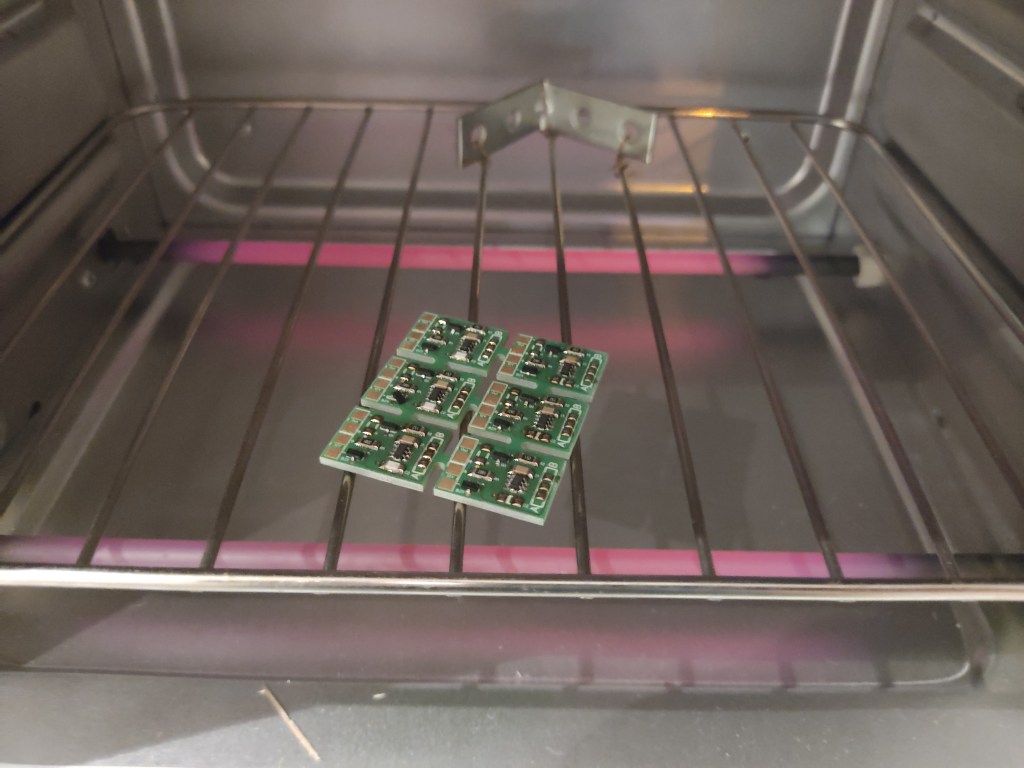
Reflow The PCB
After the soldering paste is applied and all components are positioned with the help of tweezers, the whole thing goes into my unmodified 15€ pizza oven for +-10min.
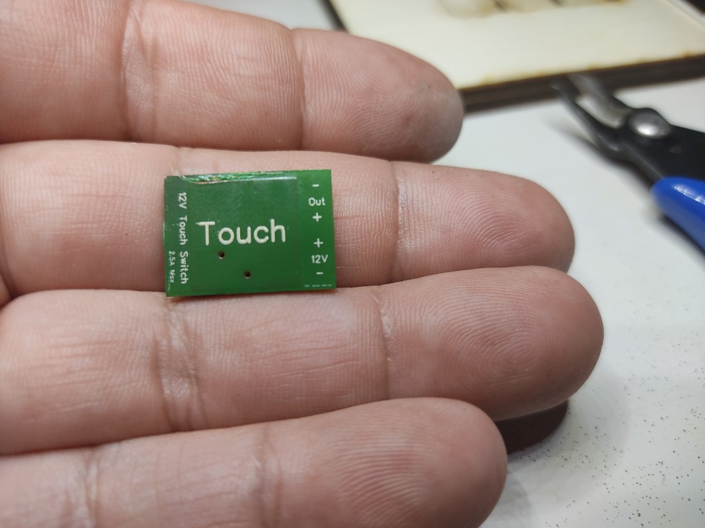
The completed board
Here is the finished PCB after cooling down. 5 on 6 without problems.
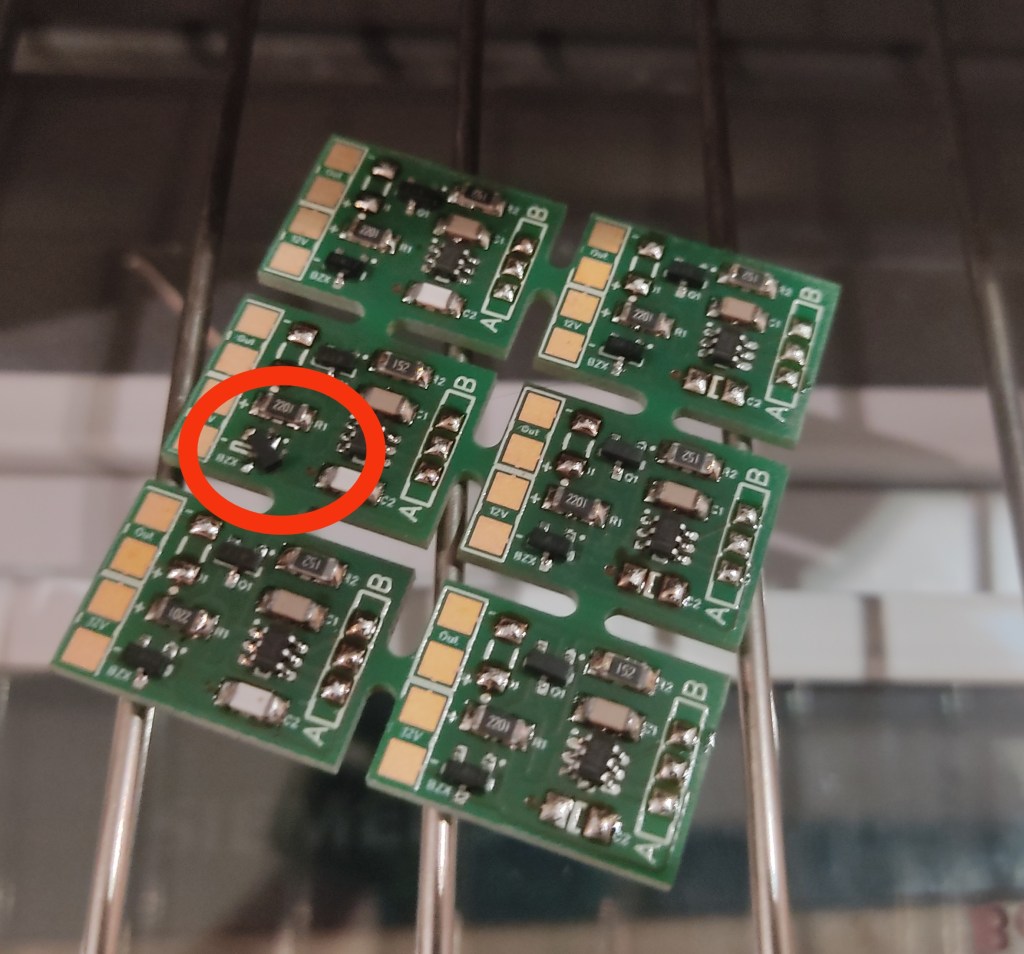
After soldering on the slipped diode,, I checked the solder joints again with a microscope. Everything looks good so far.
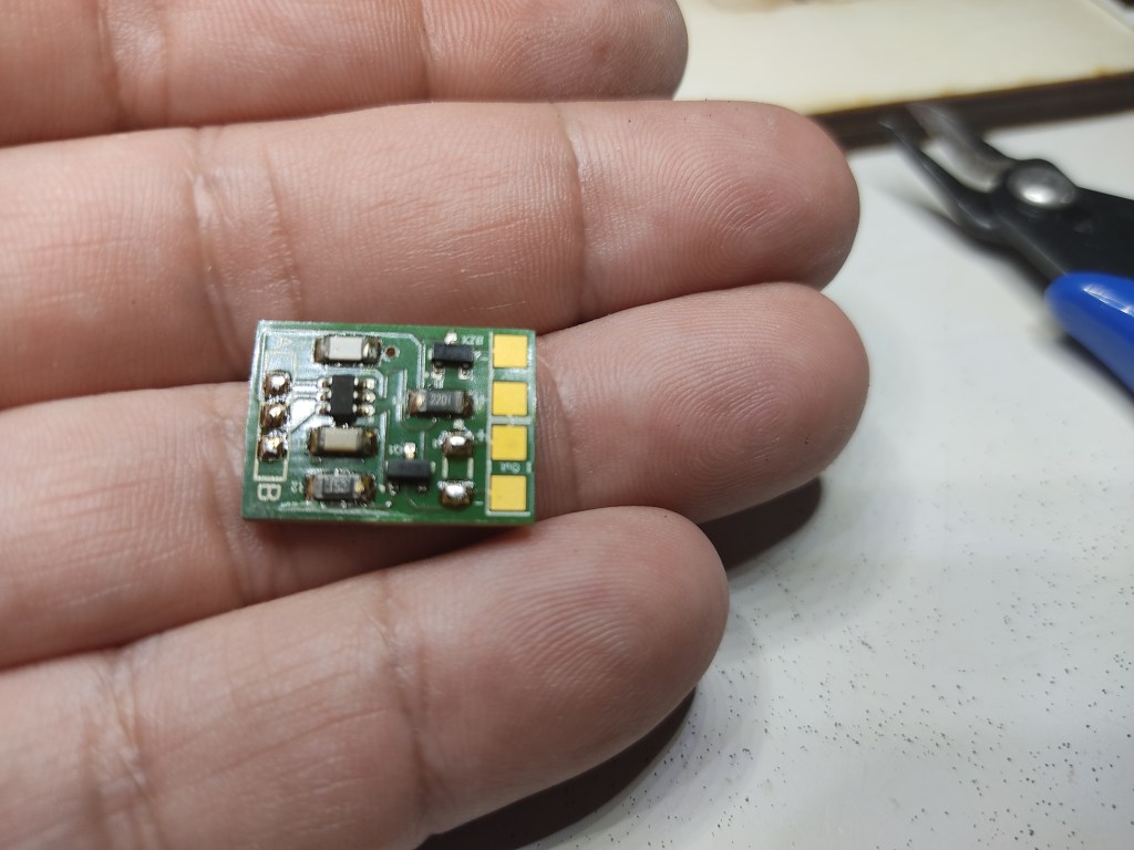
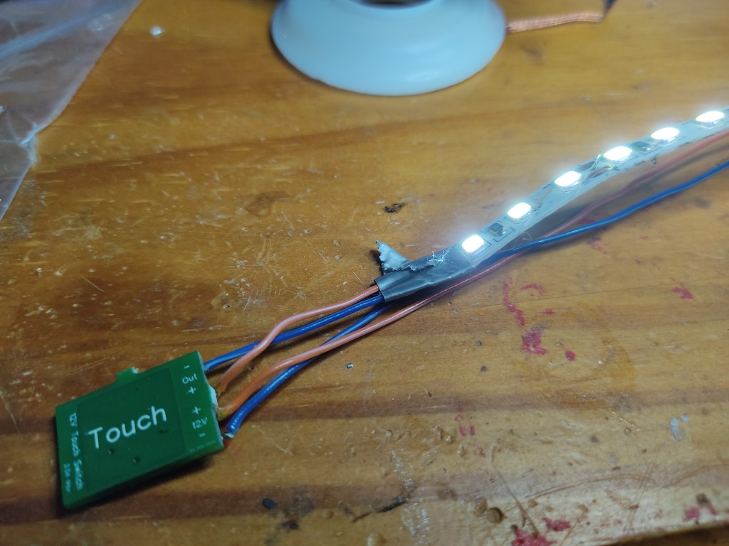
First Test Of The 12V Touch Switch.
After separating the boards, I connected a 1m long Led strip with 120 LEDs. The current consumption is a little more than 800mA. The board works as I imagined it would. Although the switching transistor can handle 3A, I still wouldn’t switch more than 2A, otherwise it gets a bit too hot during continuous operation.
Programming The Board
As on the original board, there are also solder points A and B. These are used for programming the TTP223.
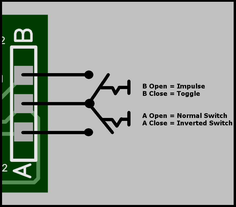
I have left out the diode on the circuit board, as it is only needed when you want to switch a relay.
The 22pf capacitor can also be left out to increase the sensitivity of the switch, for example to install it behind a thin wooden or plexiglass panel.
I hope that some of you can use these instructions. As I said, all the data including the Gerber files can be found here: https://github.com/awall9999/Capacitive-Touch-Switch-12V
