For years I have had the idea of a homemade wristwatch. I’ve been racking my brains for quite a while on how to go about it.
These points would be the biggest challenge:
The power consumption, the number of components, precise in time and the size of the watch.
So I tested several things individually, until I was satisfied with the result and I could bring the watch to life.
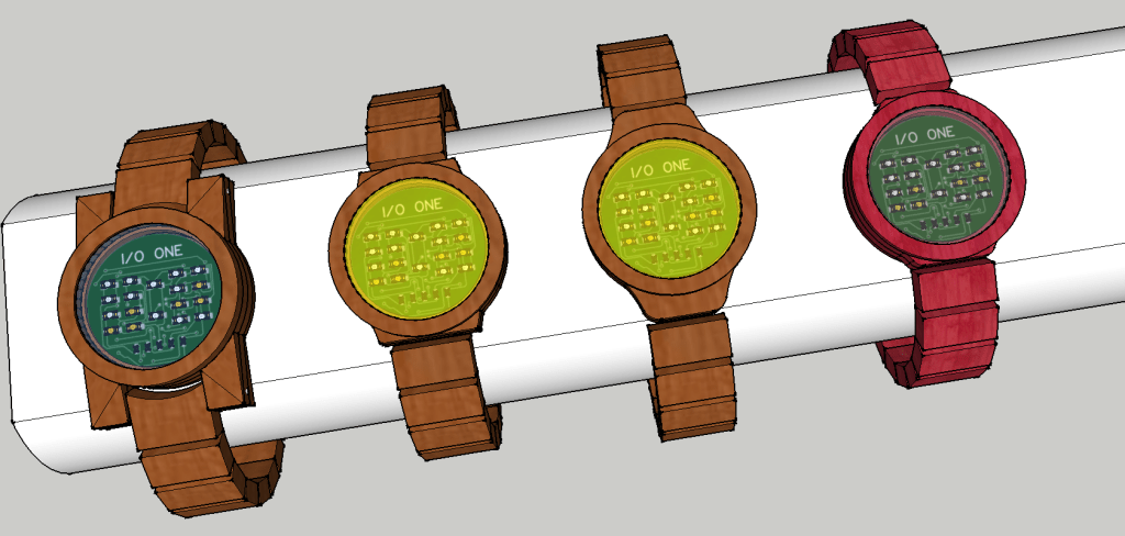
The Design Idea
The Parts
- 1 ATMEGA 328P-AU
- 1 RX8900CE UB Serial-Interface RTC-Module
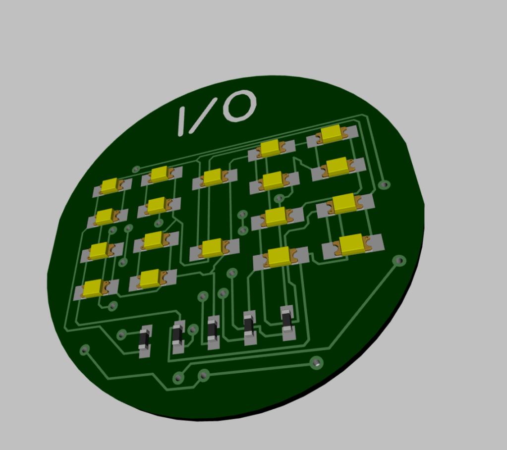
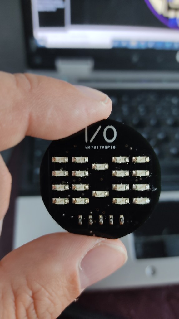
- 18 SMD LED 1206. Yellow or red. 2,3V-2,4V
- 5 SMD 0603 15R Resistors
- 1 SMD 0603 10k Resistor
- 2 SMD 0603 100nF Capacitor
- 1 Coin Cell Holder
- 1 Coin Cell CR2032
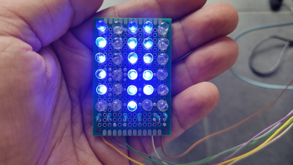
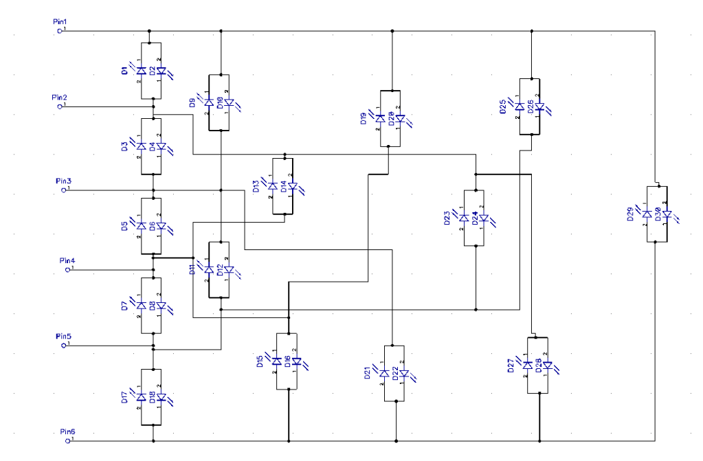
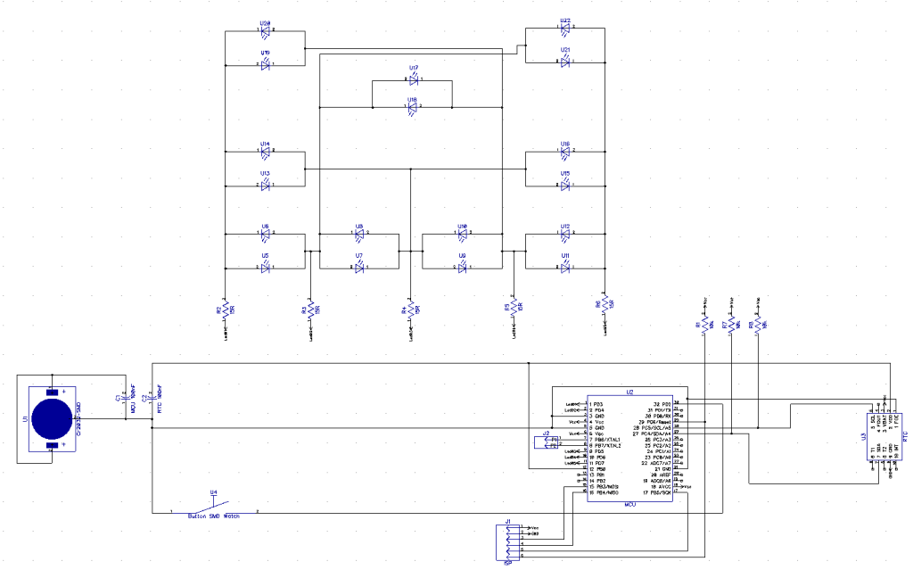
Step 1: Many Led’s, Little Power Consumption
To keep the operating current as low as possible, I decided to use “Charlieplexing” to control the LEDs. The advantage of this principle is that only one led lights up at a time and I only need a few pins to control it.
With this multiplexing method, the lamps are connected in such a way that the tristate possibility of the processor is used to make bipolar use of them.
So I first built a prototype, where I could test this extensively.
The Testcode can be found here: https://github.com/awall9999/Charlieplexing
Step 2: Deep Sleep
Now that the display is working, I started to look into the deep sleep of the processor.
There are several possibilities, but after some Google research and testing, I decided on this one.
attachInterrupt(0,wakeup, LOW); // Wakeup on Int0 LOW
ADCSRA &= ~(1 << 7); //Disable ADC
SMCR |= (1 << 2); // power down mode
SMCR |= 1; // enable sleep mode
// BOD disable
MCUCR |= (3 << 5); // Set Bods and Bodse to 1
MCUCR = (MCUCR &~(1 << 5)) | (1 << 6);
__asm__ __volatile__(“sleep”);
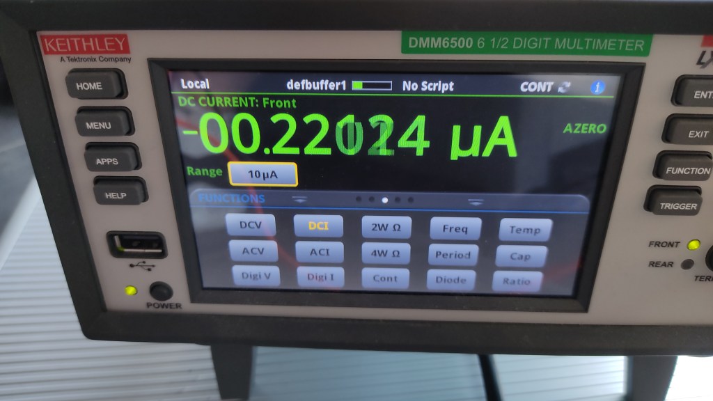
This is how I get 0.22uA without the RTC.
ADCSRA switches off the analog converter in the chip (not needed in this project anyway).
According to the datasheet, the SMRC is used to set the deep sleep (almost everything is switched off).
The chip has a way of determining when the voltage falls below a certain minimum to function. (BOD). This is switched off with the MCUCR command.
attachInterrupt(0,wakeup, LOW) This sets interrupt 0 to wake up the processor and start the void wakup().
With this power consumption, the watch should run for two years with normal use with a CR2032.
Step 3: Real Time Clock (RTC)
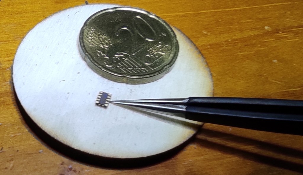
As a real time clock, I use an RX8900SA CE. This one is small, very small and you don’t need any external components for this project, even the 32kHZ crystal is integrated in the component.
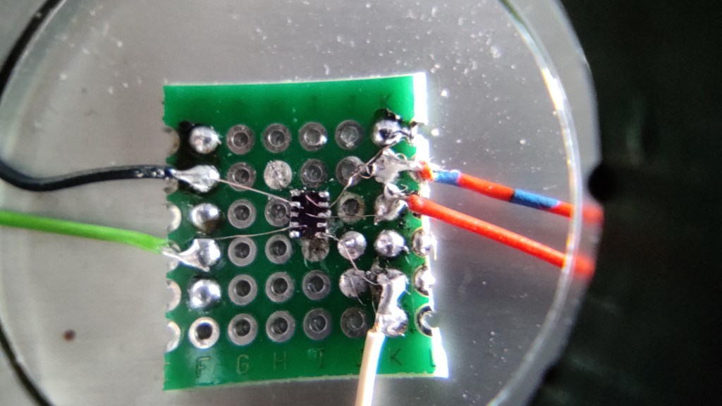
After my soldering of shame, I managed to attach the chip to a breadboard with loose wires so I could test it. It’s hard to believe, but I managed to set the time in the RTC and read it out.
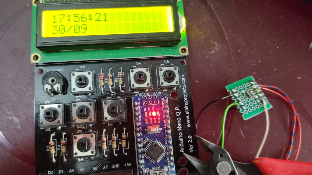
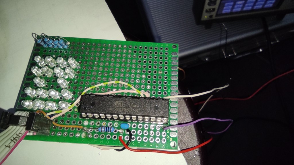
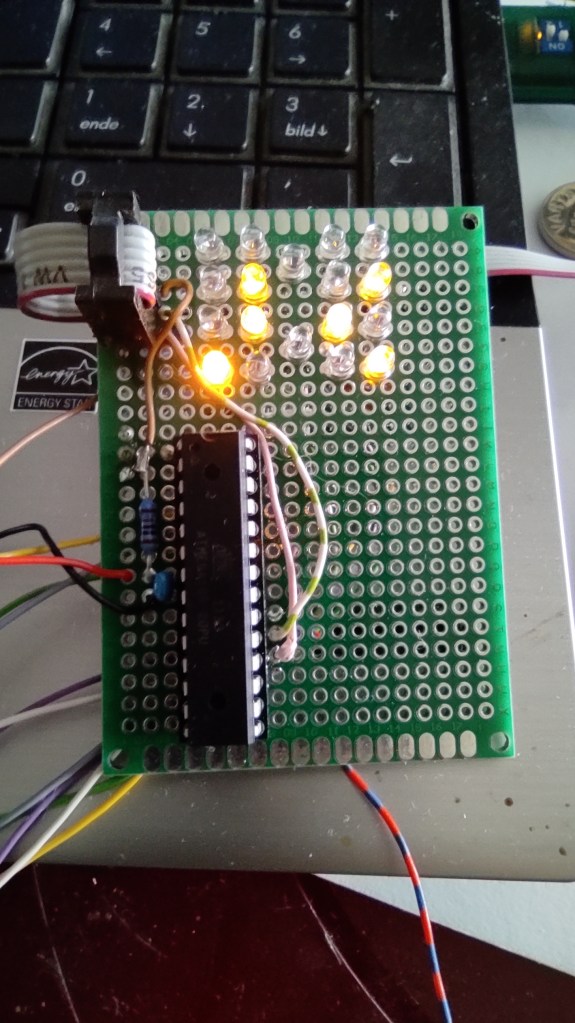
Step 4: First Prototype
First I built the whole thing with normal components on a breadboard and then on a perfboard to test everything. That way I’m sure everything works before I have a PCB made.
First we need to prepare the Atmega 328P.
It is programmed exclusively via ISP, so no bootloader is needed. It will also run on its internal oscillator at 4Mhz. Since the RTC has the exact time, this accuracy is sufficient in the MCU.
Also the BOD (minimum supply voltage) is not needed. The clock should work until the battery is empty.
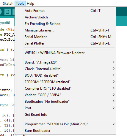
First you have to install the Minicore library: https://github.com/MCUdude/MiniCore.
Then, as shown in the screenshot, program the 328P via ISP. Either via a programming device or via an Arduino, that has been configured as an ISP.
PCB
Since everything has worked so far, I had a PCB made.
I checked it 100 times before I commissioned it, and still one, thank to God, unimportant error crept in.
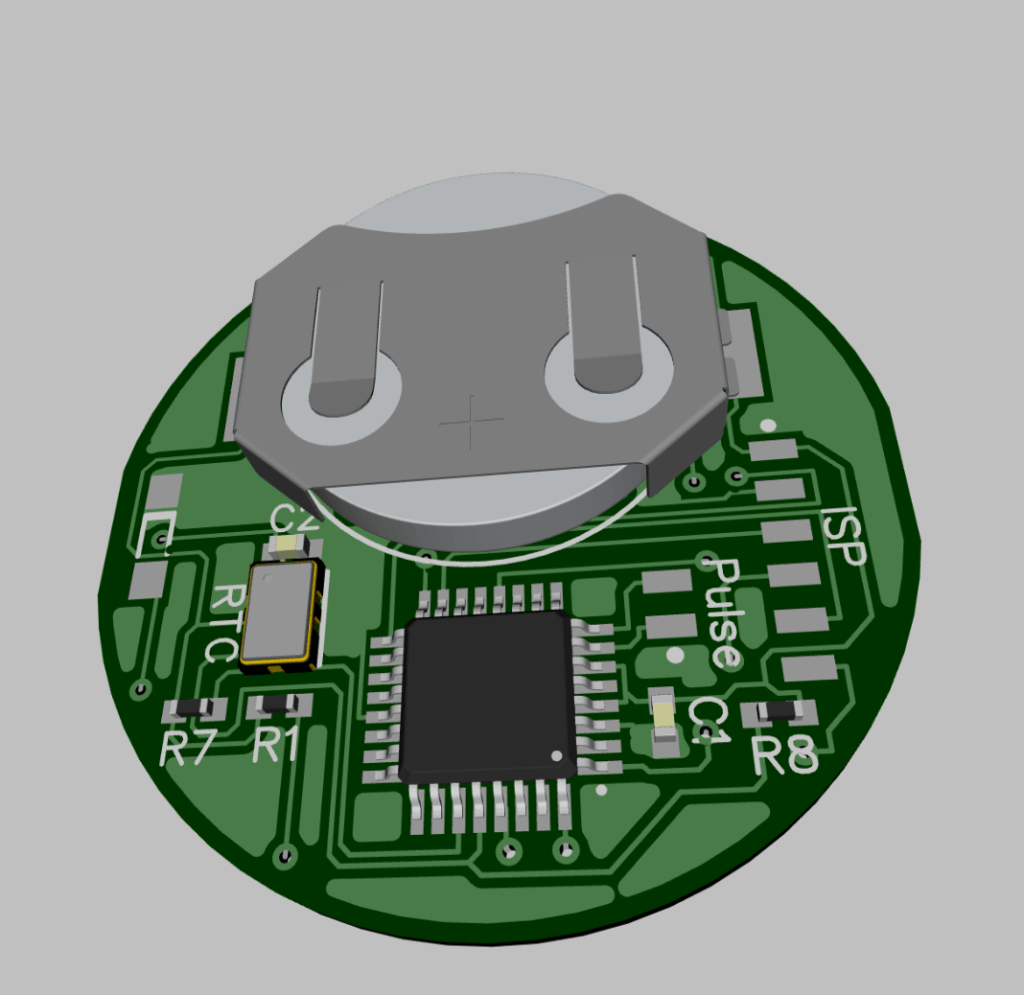

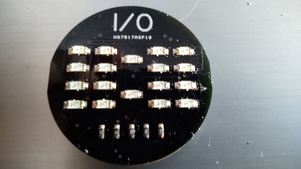
The placement
This is the first time I have a PCB with such small components. This is going to be fun.
I made a stencil with the help of my laser cutter and a plastic foil. Then I made a small mounting construction out of plywood to fix the PCB.
That worked out wonderfully.
An old electric oven was used for soldering. The backside was soldered first, and heated in the lower part of the oven. Then I put the LED’s on the front side and heated it in the upper part of the oven. It worked.
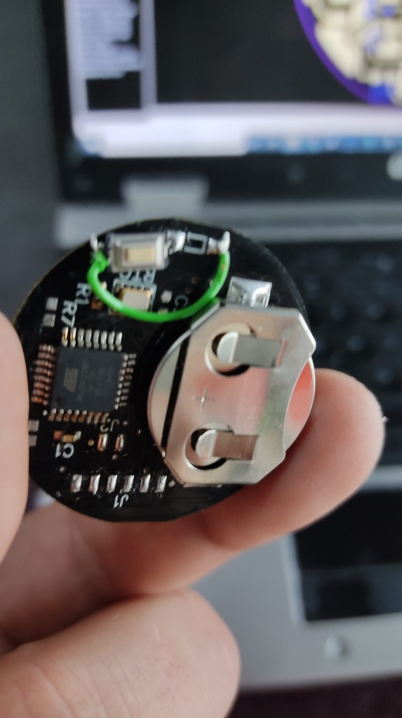
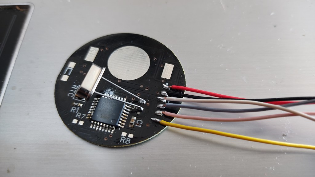
The programming.
The clock is programmed via ISP. Unfortunately, I hadn’t finished my little constriction with the spring contacts yet, so I simply soldered the wires to the board. That also works :). The Crystal was just to help to switch the fuse from external clock to internal 4Mhz clock.
Software
The Software works and can be found here: https://github.com/awall9999/Binary-Watch/
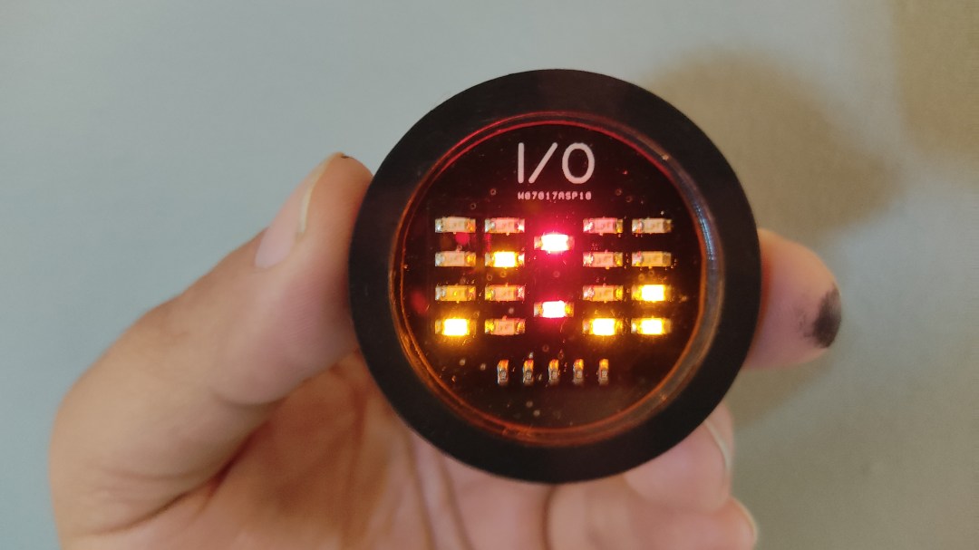
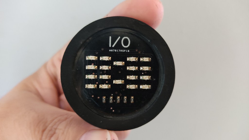
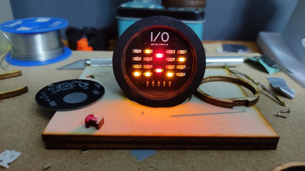
Working on the enclosure
I am still working on the case. At the moment, this is a temporary solution so that I can take the watch with me and test it continuously. It’s now some kind of Pocketwatch
Updates will follow……..


Hey there, great project! I would love to know the battery life for this.
LikeLike
It is running for one year and 8 month for now. The prototype already for ower 2 years. My calculation was 2 years by avrage use
LikeLike